Color chemistry. Substances - chameleons
A welder who is exposed to the harmful ultraviolet rays of the welding arc must take care of his health, and even more so about the safety of his eyesight. Standard shields are not able to provide the level of protection that a chameleon helmet has.
A mistake when choosing a mask for welding a chameleon can lead not only to facial burns, but also to loss of vision.
The fact that the filter is darkened does not mean the end of exposure to harmful rays. Therefore, the question of how to choose the right chameleon welding mask will be answered by the reviews of welders who have been using this type of protection for a long time. How to choose a chameleon welding mask for comfortable work?
 Unlike a standard shield, the welding chameleon has taken welder protection to a new level. The principle of operation of such a mask is liquid crystal polarization. During provocation, they change direction and interfere with UV exposure. The masks of the expensive price segment use multi-layer protection, which ensures the most uniform darkening. And an additional filter provides blocking of infrared radiation.
Sensors are built into the body of the helmet, which detect the arc and provide permanent eye protection. The whole structure is enclosed in a block, which is protected from both sides with the help of plastic light filters. You can carry out related work (grinder, hammer) without removing the protective helmet from your head. Plastic filters require replacement over time, as they are consumables. The key point of the protective process is the speed of the light filter. The response time of professional models is 1 millisecond.
 The protective properties of a chameleon directly depend on the ambient temperature. If the temperature is below minus 10 degrees, the filter operation slows down. Conscientious manufacturers indicate the maximum operating temperature in the product passport. Adjustments can be made during the workflow. The buttons have a convenient location and are easily controlled by tactile contact.
It is important to know! The mask must be stored in a heated room, otherwise its resource is reduced.
Filter classification
The light filter is the main element of the chameleon helmet. The European standard EN 379 dictates the parameters of light filters according to the regulation, which denotes qualities through a slash: 1/1/½. So, let's analyze in detail the meaning of each marking point.

Secrets of choosing a protective mask
 A chameleon helmet can be equipped with filters, or it can be sold without them.
According to the regulatory and technical documentation, the material for manufacturing should not be a current conductor, be resistant to metal splashes, and also prevent radiation from penetrating inside, thereby ensuring the welder's face is safe. Most modern masks meet these requirements.
The body of domestically produced masks is mainly made of fiber or plastic. European and American samples are original in design, and can be made in the form of an animal's head. There is an option made of leather, used mainly in cramped conditions.
In addition to the appearance, professionals advise how to choose a chameleon mask for welding according to certain parameters.

Adjusting the fastening of the mask on the head determines the comfort of using the product in the future. A comfortable viewing angle depends on the proximity of the filter to the eyes of the welder. If you decide to purchase diopter lenses, you need to get a filter with a wide viewing window, this will eliminate the need to raise the mask. Simply put, the view of the weld can be carried out over the lens.
Professional advice: Buy only those chameleon shields that are certified and have a warranty period, do not buy fakes!

Professional advice: The light filter is aimed at working with argon-arc welding, it can protect both from electric arc welding and from working with semi-automatic devices.
Popular models that the market offers
 The leading countries in the production of masks and filters are Taiwan and China. But sometimes their quality of products leaves much to be desired: the filters do not work correctly, which negatively affects the vision of the welder. The domestic manufacturer provides products of sufficient quality, but sometimes the filter does not work correctly when working with argon-arc welding.
The Korean brand OTOS, sometimes sold under the French brand GYSMATIC, has a weak point - the filter. There were cases of delamination, as well as the appearance of spots and microcracks.
The masks offered by Europe are higher in price, but their quality is consistently high. The filter of one sample may not be suitable for another product. Next, several brands that produce quality masks that have corresponding quality certificate:

Professional advice. If during welding there is discomfort in the form of burning, fatigue and tearing of the eyes, you should stop using such a mask. Most likely a low quality product.
Now you know all the secrets of the chameleon shield. Not only the health of the welder's eyes, but also the quality of the current work depends on high-quality protection.


 Back forward
Attention! The slide preview is for informational purposes only and may not represent the full extent of the presentation. If you are interested in this work, please download the full version.
Lesson Objectives:
- repeat the algorithm for compiling the OVR by the electronic balance method and reveal the essence of the MPR semi-reaction method.
- to show the advantages in the formation of skills for predicting the direction of OVR in solutions using manganese compounds as an example.
- consolidate skills in compiling OVR equations occurring in various environments.
- to teach how to apply the acquired knowledge to solve specific problems.
Lesson objectives.
- Prepare students for task 36 of the exam in chemistry
- Planned result
Subject:
- know RIA, rules for compiling RIA;
- be able to Determine the nature of the medium, the conditions for the occurrence of OVR, the initial and products of formation, the oxidizing agent and the reducing agent, draw up an electronic balance and use the semi-reaction method, conduct an experiment and draw a conclusion based on the experiment.
Metasubject:
- be able to Organize their activities, determine their goals and objectives, choose the means of achieving the goal and apply them in practice, evaluate the results; establish causal relationships, build logical reasoning, draw conclusions; ability to create models and schemes; the ability to organize educational cooperation and joint activities with the teacher and peers, work individually and in a group.
Personal: Formation of a responsible attitude to learning, readiness and ability of students for self-development and self-education based on motivation for learning and cognition; formation of communicative competence in communication and cooperation with peers in the process of learning activities.
Equipment and reagents:
- personal computer, projector, presentation
- Potassium permanganate solution, crystalline potassium permanganate, sulfuric acid solution, alkali solution, potassium iodide solution, sodium sulfite, 5-10% hydrogen peroxide solution
- Large test tubes placed in a demonstration stand with a white background, a device for obtaining gases, a receiver flask, an iron stand, a spirit lamp, a splinter, matches, test tubes in a universal stand on each table, a glass rod
- Appendix 1 “Compounds of the element manganese: oxidizing and reducing agents, calculation of oxidation states”
- Appendix 2 “Algorithm for compiling OVR equations using the electronic balance method”
- Appendix 3 “Algorithm for compiling OVR equations by the ion-electron method”
- Appendix 4 “Oxidative and reducing properties of hydrogen peroxide depending on the nature of the medium. Instructions for performing a laboratory experiment”.
Lesson type: assimilation of new knowledge using existing knowledge and skills, followed by generalization and systematization.
Forms used in the lesson
- Explanation (explanatory and illustrative)
- reasoning (partial-exploratory)
- general characteristics (problematic)
Methods used in the lesson
- verbal (conversation, explanation)
- visual (experiments, computer presentation, information applications)
- practical (demonstration and independent performance of experiments).
Lesson plan.
- Knowledge update.
- Repetition of the main theoretical concepts of the topic.
- Definition of the environment (acidic, neutral or alkaline) in which the reaction takes place.
- Electronic and ion-electronic method for compiling OVR equations
- Consolidation of acquired knowledge
During the classes
1. Actualization of knowledge.
Preparation for task 36 consists of several elements:
The study of theoretical material, individual consultations with the teacher and the implementation of tasks based on this methodological material.
Before starting work, it is necessary to master the basic terms, definitions, concepts and master the technique of chemical calculations.
In the task, a reaction scheme is proposed, and the formulas of one or two substances are replaced by dots.
All tasks 36 can be divided into three types:
The teacher projects diagrams onto the screen using a video projector Slide 2
2. Repetition of the material covered
In the program of the basic school, you have already touched on the main issues necessary to complete assignment 36.
You know what chemical reactions are redox reactions and that in OVR one of the participants is oxidized. This is a reducing agent, i.e. it donates electrons and increases its oxidation state. The other one is being restored. This is an oxidizing agent, i.e. it draws a valence pair of electrons to itself, lowers its oxidation state.
slide 3 The teacher projects diagrams onto the screen using a video projector
We carry out the task. Students have an application on their desks Appendix 1
Let's do the exercise:
- determination of the oxidation state of elements by the formula
- the structure of the manganese atom, determine the possible oxidation states of the element, its oxidizing and reducing ability.
- fill in the table according to the types of chemical reactions
- form the conclusion
Students complete the table. They conclude: all substitution reactions and reactions in which simple substances are present belong to OVR. Consider the structure of the manganese atom. They make a conclusion.
3. Determination of the medium (acidic, neutral or alkaline) in which the reaction proceeds.
When you start this task, you, logically, must identify the missing substances. To do this, it is necessary to know the main oxidizing and reducing agents, as well as the products of their reduction or oxidation.
In addition, in order to add missing substances, one should take into account the medium in which the redox reaction occurs.
You can define the environment
A) by products of reduction of the oxidizing agent (for example, manganese)
Permanganates are strong oxidizing agents, and, depending on the pH of the medium:
The teacher projects diagrams onto the screen using a video projector, conducts an experiment
slide 4, 5, 6 Demonstration experiment “Chemical chameleon”
Reduction of potassium permanganate with sodium sulfite in various media.
4. Procedures for selecting coefficients in equations
As for the actual procedure for selecting the coefficients in the equations, the electron balance method can be used, and for reactions in solutions, the so-called semi-reaction method, or electron-ion method, is convenient.
The teacher projects diagrams onto the screen using a video projector Slide 7,8,9
Compilation of OVR equations by the electronic balance method
The electron balance method is based on a comparison of the oxidation states in the initial and final substances, when all the initial substances and reaction products are known. You have already used this method when working in lessons in grades 8-9.
Appendix 2
Whiteboard work: Equalize the reactions using the electron balance method, determine the oxidizing agent and reducing agent. slide 7,8,9
They conclude: Using the electronic balance method, it is convenient to arrange the coefficients if the starting materials and reaction products are known, i.e. complete reaction schemes are given.
Semi-reaction method, or electron-ion.
When using the semi-reaction method (electron-ion balance), it should be borne in mind that in aqueous solutions, the binding of excess oxygen and the addition of oxygen by the reducing agent occur differently in acidic, neutral, and alkaline media.
The teacher projects diagrams onto the screen using a video projector. Performs experiments.
Students have applications on their desks. Appendix 3 slide 10,11
D demonstration experience. Reduction of potassium permanganate with potassium iodide in various media. "Chemical Chameleon"
The teacher projects diagrams onto the screen using a video projector, students have diagrams on their desks for convenience.
Whiteboard work: Equalize the reactions using MPR, determine the oxidizing agent and reducing agent.
One reaction is performed by the teacher, two are left for independent work of students.
slide 12,13,14
We conclude:
Having considered the method of electron-ion balance or the method of semi-reactions, the following advantages of this method can be distinguished:
5. Consolidation of acquired knowledge
Reactions - disproportionation.
The teacher projects diagrams onto the screen using a video projector. Performs experience.
Demonstration experiment “Chemical chameleon” slide 15, 16
Description:
For the experiment, you need a test tube with a gas outlet tube. Crystalline potassium permanganate (potassium permanganate) was poured into a test tube. When heated, potassium permanganate decomposes, the released oxygen enters through the gas outlet tube into the receiver flask. Oxygen is heavier than air, so it does not leave the flask and gradually fills it. If you lower a smoldering torch into a flask with collected oxygen, then it will flare up brightly, because. oxygen supports combustion.
The reaction equation:
2KMnO 4 \u003d K 2 MnO 4 + MnO 2 + O 2
After the end of the experiment and cooling of the test tube, several milliliters of water are poured into it, the contents are thoroughly shaken and the color of the formed substances is observed (K 2 MnO 4 is green and MnO 2 is dark brown).
K 2 Mn +6 O 4 + H 2 O -> KMn +7 O 4 + Mn +4 O 2 + KOH
When strongly diluted with water, a self-oxidation-self-recovery reaction occurs. The color will change from green to red-violet and a brown precipitate will form.
Independent work in notebooks: Level the reactions using MPR, determine the oxidizing agent and reducing agent. slide 15,16
Form output: These are reactions where the oxidizing agent and reducing agent are the same element that is part of one molecule.
We independently conduct an experiment and write an equation using the half-reaction method
The teacher explains that hydrogen peroxide can exhibit oxidizing and reducing properties in both acidic and alkaline environments.
(peroxides can be both oxidizing and reducing agents, peroxide electrons can move from one molecule to another:
H 2 O 2 + H 2 O 2 \u003d O 2 + 2H 2 O.)
Students perform a laboratory experiment and draw a conclusion about the manifestation of hydrogen peroxide oxidizing and reducing properties depending on the environment.
Note. For the experiment, a 3% solution of hydrogen peroxide is used, which can be purchased at a pharmacy, as well as a solution of potassium permanganate.
The technique of the experiment is simple and does not require much time. .
The teacher projects diagrams onto the screen using a video projector. For convenience, students have an application on their desks. Appendix 4 Slide 17
Laboratory work: “Reduction of permanganate with hydrogen peroxide” “Chemical chameleon” - Turning a raspberry solution into a colorless one”
They conclude: In this case, hydrogen peroxide exhibits reducing properties, and potassium permanganate - oxidizing.
6. Homework: Slide 18
AMPovichok
ADULT
OTHER VOLTAGE AMPLIFIERS
CHAMELEON
However, Lanzar's circuitry can be somewhat changed, significantly improving performance, increasing efficiency without using an additional power source, if you pay attention to the weaknesses of an existing amplifier. First of all, the reason for the increase in distortion is the changing current flowing through the transistors, and changing over fairly large ranges. It has already been found out that the main amplification of the signal occurs in the last stage of the UNA, which is controlled by the transistor of the differential stage. The range of change in the current flowing through the differential stage is quite large, since it needs to open the transistor of the last stage of the UNA, and the presence of a non-linear element as a load (base-emitter junction) does not contribute to maintaining the current with a changing voltage. In addition, in the last stage of the UNA, the current also varies over a fairly wide range.
One of the solutions to this problem is the introduction of a current amplifier after the differential stage - a banal emitter follower, which unloads the differential stage and allows you to more clearly control the current flowing through the base of the last UNA stage. To stabilize the current through the last stage of the UNA, current generators are usually introduced, however, this option will be postponed for the time being, since it makes sense to try a lighter option, which significantly affects the increase in efficiency.
The idea is to use a voltage boost, but not for a separate stage, but for the entire UNA. One of the first options for implementing this concept was the power amplifier A. Ageev, quite popular in the mid-80s, published in RADIO No. 8, 1982 (Figure 45, model AGEEV.CIR).
Figure 45
In this circuit, the voltage from the output of the amplifier is supplied, through the divider R6 / R3, for the positive shoulder and R6 / R4 for the negative, to the power terminals of the operational amplifier used as the UNA. Moreover, the level of constant voltage is stabilized by D1 and D2, but the value of the variable component just depends on the amplitude of the output signal. Thus, it was possible to obtain a much larger amplitude at the output of the op-amp, without exceeding the value of its maximum supply voltage, and it became possible to power the entire amplifier from + -30 V with a maximum supply voltage of +-15 V). If you switch to mode TRANSITION STUDY, then the following waveforms will appear on the "oscilloscope screen":

Figure 46
Based on the idea of floating power, which was used by Ageev, as well as the introduction of a current amplifier after the differential stage, a power amplifier was designed, the circuit of which is shown in Figure 47, model Chameleon_BIP.CIR, called Chameleon, since it allows you to adjust the main modes to the used supply voltage - adjustment of the quiescent current of the last UNA stage.

Figure 47 (ENLARGE)
In addition to the circuit solutions described above, another one was introduced - the regulation of the quiescent current of the last stage of the UNA, moreover, with thermal stabilization elements. The adjustment of the quiescent current of the last stage of the UNA is carried out by a trimming resistor R12. On transistors Q3 and Q6, emitter followers are made that unload the differential stage, on the chains R20, C12, R24, R26 for the positive shoulder and on R21, C13, R25, R27 for the negative shoulder, a voltage boost for UNA is made. In addition to increasing the efficiency, the voltage boost performs another secondary function - due to the fact that the actual signal amplitude decreased, the range of current change through the last cascade of the UNA also decreased, which made it possible to abandon the introduction of a current generator.
As a result, the THD level at an input voltage of 0.75 V was:

Figure 49
As can be seen from the resulting graph, the THD level decreased by almost 10 times in relation to Lanzar with PBVK.
And here the hands begin to itch - having such a low THD level, I want to increase my own gain coffin, add more terminal transistors and "overclock" this amplifier to the level of a variety one with an output power of about 1 kW.
For experiments, you should open the file Chameleon_BIP_1kW.CIR to conduct a series of primary "measurements" - quiescent currents, the value of the constant voltage at the output, frequency response, THD level.
The results are impressive, but...
Just at this moment, practice intervenes in theory, and not in the best way.
To find out where the problem lurks, you should run DC CALCULATION and turn on the power dissipation display mode. You should pay attention to the differential stage transistors - about 90 mW is dissipated on each. For the TO-92 case, this means that the transistor begins to heat up its case, and given that both transistors should be as close to each other as possible in order to warm up evenly and maintain equal quiescent currents. It turns out that the "neighbors" not only warm themselves, but also warm each other up. Just in case, it should be recalled that when heated, the current through the transistor increases, therefore, the quiescent current of the differential stage will begin to increase and change the operating modes of the remaining stages.
For clarity, set the final stage quiescent current to 200 mA, and then assign a different name to transistors Q3 and Q6, add a lower dash and one right in the designation window to get the following: 2N5410_1 and 2N5551_1. This is necessary to exclude the influence of the variable parameters of the differential stage transistors. Next, you need to set the temperature of the differential cascade transistors to, for example, 80 degrees.
As can be seen from the resulting calculations, the quiescent current has decreased, and by so much that a "step" will already be observed. It is not difficult to calculate that with an initial quiescent current of 50 mA, the quiescent current of the final stage with the heating of the differential stage will become almost zero, i.e. the amplifier will go to class B.
The conclusion suggests itself - it is necessary to reduce the dissipated power of the differential stage, but this can only be done by reducing the quiescent current of these transistors, or by reducing the supply voltage. The first will cause an increase in distortion, and the second - a decrease in power.
There are two more options for solving the problem - you can use heat sinks for these transistors, but this method, despite its performance, does not add much reliability - constant purge of the case is required to prevent the heatsinks from heating to critical temperatures in a poorly ventilated case. Or, once again, change the circuitry.
However, before the next change, this amplifier should still be finalized, namely, increase the ratings of R24 and R25 to 240 ohms, which will entail a slight decrease in the supply voltage of UNA, and of course, reduce the supply voltage to + -90 V, and, well, slightly reduce its own gain coff .

Cooling of the differential stage of the Chameleon amplifier of the previous version
As a result of these manipulations, it turns out that this amplifier at an input voltage of 1V is capable of developing about 900 W at a load of 4 Ohms, at a THD level of 0.012%, and at an input voltage of 0.75 V - 0.004%.
To insure the transistors of the differential cascade, you can put on pieces of the tube from the telescopic antenna of the radio. This requires 6 pieces 15 mm long and 5 mm in diameter. Place thermal paste inside the tube, solder the tubes together, after putting them on the differential stage transistors and the emitter followers following them, and then connect them to the common one.
After these operations, the amplifier turns out to be quite stable, but it is still better to use it at a supply voltage of + -80 V, since an increase in the mains voltage (if the power supply is not stabilized) will increase the power supply of the amplifier and there will be a margin for temperature conditions.
Radiators for the differential stage can not be used if the supply voltage does not exceed + -75 V.
The printed circuit board drawing is in the archive, the installation is also in 2 floors, the performance check and adjustment are the same as in the previous amplifier.
VP AMP or STORM or?
Next, an amplifier better known as "V. PEREPELKIN AMPLIFIER" or "VP AMPLIFIER" will be considered, however, putting OR in the title of the chapter in no way intended to encroach on V. Perepelkin's work on designing a series of his amplifiers - a lot of work has been done and in In the end, we got pretty good and versatile amplifiers. However, the circuitry used has been known for a long time and the attacks on STORM about overdrawing, cloning are not entirely fair and further consideration of circuitry solutions will provide comprehensive information about the design of both amplifiers.
In the previous amplifier, there was a problem with the self-heating of the differential stage at high supply voltages and the maximum power that can be obtained using the proposed circuitry was indicated.
The heating of the differential stage itself can be excluded, and one of the solutions to this problem is to divide the dissipated power into several elements, but the most popular is to turn on two transistors connected in series, one of which works as part of the differential stage, the second is a voltage divider.
Figure 60 shows diagrams using this principle:

Figure 60
In order to understand what happens with this solution, you should open the WP2006.CIR file, which is an amplifier model from V. Perepelkin, known on the Internet as WP.
The amplifier uses a UN, built according to the principles of the examples above, but slightly modified - the output stage of the UNA does not work for a thermal stabilization transistor, as is usually the case, but is actually a separate device with one output - the junction point of the collectors of transistors Q11 and Q12 (Figure 61) .

Figure 61(ENLARGE)
The circuit contains the actual ratings of one of the amplifiers, however, the model had to select the resistor R28, otherwise the output of the amplifier had an unacceptable constant voltage. When checking DC CALCULATION the thermal modes of the differential stage are quite acceptable - 20 ... 26 mW is allocated on the differential stage. The transistor Q3 installed above dissipates a little more than 80 mW, which is also within the norm. As can be seen from the calculations, the introduction of transistors Q3 and Q4 is quite logical, and the problem of self-heating of the differential stage is solved quite successfully.
It should be noted here that Q3, however, like Q4, can dissipate a little more than 100 mW, since the heating of this transistor affects the change in the quiescent current of only the last stage of the UNA. In addition, this transistor has a rather rigid binding to the base current - for a constant voltage it operates in the emitter follower mode, and for a variable component it is a cascade with a common base. But the amplification of the alternating voltage is not large. The main load to increase the amplitude is still on the last cascade of the UN and higher requirements are still imposed on the parameters of the transistors used. The final stage uses a voltage boost organized on capacitors C16 and C17, which made it possible to significantly increase the efficiency.
Given the nuances of this amplifier and the desire to use a traditional output stage, the next model was created - Stormm AB.CIR. The schematic diagram is shown in Figure 62.

Figure 62 (ENLARGE)
To increase the efficiency in this amplifier, a floating supply for the UNA was used, an integrator on X2 was added to automatically maintain zero at the output, and an adjustment of the quiescent current (R59) of the last stage of the UNA was also introduced. All this made it possible to reduce the thermal power released on the transistors of the differential cascade to the level of 18 mW. In this version, the overload protection of the Lynx-16 amplifier was used (it is understood that Q23 controls the thyristor, which in turn controls the optocoupler connecting pins T4 and T5). In addition, another not quite traditional move was used in the last amplifier - high-capacity capacitors were installed in parallel with resistors R26 and R27, which made it possible to significantly increase the gain coefficient of this stage - it's no secret that resistors in emitter circuits are used for thermal stabilization and the more the value of this resistor, the cascade will be more thermally stable, but the coff gain of the cascade is proportionally reduced. Well, since this section is quite responsible, then as capacitors C15 and C16 you need to use capacitors that can recharge quickly enough. Ordinary electrolytes (TK or SK) only introduce additional distortion due to their inertia, but capacitors used in computer technology, often referred to as pulsed (WL), do an excellent job with their tasks.(Figure 63).

Figure 63
All these changes made it possible to increase thermal stability, as well as quite seriously reduce the THD level (you can verify this, as well as check the degree of thermal stability yourself).
The schematic diagram for the two-block version is shown in Figure 64, model Stormm_BIP.CIR

Figure 64 (ENLARGE)
The name STORM was given for the possibility of a painless increase in the supply voltage to + -135, which in turn makes it possible, using separate switches, to transfer the amplifier to class G or H, and these are powers up to 2000 watts. Actually, the VP-2006 amplifier also translates well into these classes, more precisely, the progenitor was designed for class H, but since such large powers are practically not needed in everyday life, and the potential in this circuitry is quite good, the switches were removed and a pure class AB appeared .
HOLTON AMPLIFIER
The principle of separation of the dissipated power of the differential stage is also used in the rather popular Holton amplifier, the circuit diagram of which is shown in Figure 65.

Figure 65 (ENLARGE)
The amplifier model is in the HOLTON_bip.CIR file. It differs from the classic version by the use of bipolar transistors as the final stage, therefore it is strongly recommended to use field effect transistors as the penultimate stage.
The values of the resistors R3, R5, R6, R7, R8 are also slightly corrected, the zener diode D3 is replaced with a higher voltage one.. All these replacements are caused by the need to return the quiescent current of the stage differential to a level that provides minimal distortion, as well as to more evenly distribute the dissipated power. When using an amplifier with a power supply less than that used in this model, it is necessary to select these elements in such a way that the necessary quiescent current of the differential stage returns again.
Of the circuitry features - a current generator in a differential stage, the symmetry of the passage of the input signal with respect to the feedback signal. When the UNA is powered from a separate power source, it is possible to achieve a really maximum output power.
The appearance of the finished amplifier (300 W version with bipolar output) is shown in Figures 66 and 67.

Figure 66

Figure 67
ALMOST NATALY
This is a rather simplified version of the high-quality NATALY amplifier, however, the parameters of the simplified version turned out to be quite good. Model in the file Nataly_BIP.CIR, schematic diagram in Figure 68.

Figure 68 (ENLARGE)
Sukhov's remix because this is the very same amplifier by VV N. Sukhov, it is only performed according to a symmetrical scheme and uses a completely imported equipment. Schematic diagram in Figure 69, model in file Suhov_sim_BIP.CIR.

Figure 69 (ENLARGE)
I would like to dwell on this model in more detail, since it was embedded in metal (Figure 69-1).

Figure 69-1
It can be seen even with the naked eye that the UN looks somewhat peculiar - details are soldered on top, the purpose of which is worth explaining. They are designed to calm this amplifier, which turned out to be very prone to excitement.
By the way, it was not possible to calm him completely. Stability appears only at a quiescent current of the final stage of the order of 150 mA. The sound is not bad at all, the THD dial meter, which has a limit of 0.1%, practically does not show any signs of life, and the calculated values are also very indicative (Figure 69-2), but the reality says something completely different - either a serious processing of the board is required, the board in which most of the recommendations on the layout of boards were observed, or the rejection of this circuitry.

Figure 69-2
To say that this amplifier failed? You can, of course you can, but it is THIS amplifier that is an example of the fact that modeling is far from reality and a real amplifier can differ significantly from the model.
Therefore, this amplifier is written off as a puzzle, and several more are added to it, which were used together with the same UN.
The proposed options have an end stage operating with its own environmental protection, i.e. having their own coffee. gain, which allows you to reduce the gain of the UNA itself and, as a result, reduce the THD level.

Figure 69-3 Schematic diagram of an amplifier with a bipolar final stage (ZOOM)

Figure 69-4 THD diagram of Figure 69-3

Figure 69-4 Schematic diagram with field output stage (ZOOM)

Figure 69-6 THD diagram of Figure 69-5
Minor improvements, the introduction of a buffer amplifier on a good op-amp with repeaters, to increase the load capacity, did not have a very bad effect on the parameters of this amplifier, which, in addition, is equipped with a balanced input. Model VL_POL.CIR , circuit diagram in Figure 70. Models VL_bip.CIR - bipolar variant and VL_komb.CIR - with poles in the penultimate cascade.

Figure 70 (ENLARGE)
Quite a popular amplifier, however, the model of the original version did not impress (file OM.CIR), so some changes were made while regrinding the UN for the proposed design. The results of the change can be found using the file with the OM_bip.CIR model, the schematic diagram is shown in Figure 71.

Figure 71 (ENLARGE)
TRANSISTORS
The models use transistors, which may not be available everywhere, so it would not be fair not to supplement the article with a list of transistors that can be used in real amplifiers.
| NAME, STRUCTURE | U ke, V |
I k, A |
h 21 |
F 1.MHz |
P k, W |
||
TO-220 (layer) |
|||||||
TO-220 (layer) |
|||||||
TO-220 (layer) |
|||||||
With reference data, everything seems to be clear, however ...
The rampant profit race is causing problems not only at the retail level in a tent in the market, but also in serious enterprises. The license for the release of IRFP240-IRFP920 was bought by Vishay Siliconix Corporation and these transistors are already different from those that were previously produced I international R ectifier. The main difference is that even in one batch, the gain of the transistors varies and is quite strong. Of course, it will not be possible to find out for what reason the quality has decreased (deterioration of the technological process or casting to the Russian rejection market), so you have to use what is available and from THIS you need to choose what is suitable.
Ideally, of course, both the maximum voltage and maximum current should be checked, however, the main parameter for the amplifier builder is the gain coefficient and it is especially important if several transistors connected in parallel are used.
Of course, it is possible to use the amplification coefficient meter available in almost every digital multimeter, but there is only one problem - for transistors of medium and high power, the amplification coefficient strongly depends on the current flowing through the collector. In multimeters, the collector current in the transistor tester is a few milliamps and its use for medium and high power transistors is tantamount to guessing on coffee grounds.
It is for this reason that a stand was assembled for rejecting power transistors, not even for rejection, but for selection. The schematic diagram of the stand is shown in Figure 72, the appearance - Figure 73. The stand is used for selection of transistors with the same gain coefficient, but not how to find out the value of h 21.

Figure 73

Figure 74
The stand was assembled within three hours and it literally used what was lying in the "ANTIQUES" box, i.е. something that is not difficult to find even for a novice solderer.
Indicator - level indicator of a reel-to-reel tape recorder, type M68502. The indicator was opened at the place where the top and bottom covers were glued, the standard scale was removed, and instead a scale was pasted, which can be printed using the DOK document and contains reminders for switching the operating mode. The sectors are filled with colored markers. The indicator covers were then glued together with SUPER GLUE (Figure 75).

Figure 75
Toggle switches - in fact, any toggle switches with two fixed positions, and one must ALWAYS have TWO switching groups.
Diode bridge VD10 - any diode bridge with a maximum current of at least 2 A.
Mains transformer - any transformer with a power of at least 15 W and an alternating voltage of 16 ... 18 V (the voltage at the KRENka input should be 22 ... 26 V, the KRENka must be connected to the radiator and preferably with a good area).
C1 and C2 have a sufficiently large capacitance, which ensures that the needle does not shake during measurements. C1 for 25 V, C2 for 35 or 50 V.
Resistors R6 and R7 are pressed through a mica gasket to the radiator on which Krenka is installed, coated with plenty of thermal paste and pressed with a strip of fiberglass using self-tapping screws.
The most interesting is the design of the clamps for connecting the outputs of the transistors under study. For the manufacture of this connector, a strip of foil fiberglass was required, in which holes were drilled at a distance from the output of the TO-247 case transistor, and the foil was cut with a clerical cutter. Three knives from the SCART-MAMA television connector were soldered into the holes on the side of the foil. The knives were stacked together, almost close to each other (Figure 76).

Figure 76
The distance "L" is chosen in such a way that the bodies of transistors TO-247 (IRFP240-IRFP9240) and TO-3 (2SA1943-2SC5200) are put on the fixing pin.

Figure 77
Using the stand is quite simple:
When selecting field-effect transistors, the mode is set MOSFET and the type of transistor is selected - with an N channel or a P channel. Then the transistor is put on a hairpin, and its leads are applied to the contact blades of the connector. Then a variable resistor, let's call it CALIBRATION, the arrow is set to the middle position (which will correspond to the current flowing through the transistor 350-500 mA). Next, the transistor is removed and the next candidate is installed in its place for use in the amplifier and the position of the arrow is memorized. Next, a third candidate is identified. If the arrow deviated in the same way as on the first transistor, then the first and third can be considered basic and the transistors can be selected according to their gain coefficient. If the arrow on the third transistor deviated in the same way as on the second one and their readings differ from the first one, then recalibration is performed, i.e. re-setting the arrow to the middle position and now the second and third transistors are considered basic, and the first is not suitable for this batch of sorting. It should be noted that there are quite a lot of identical transistors in a batch, but there is a chance that recalibration may be required even after selecting an already solid number of transistors.

Figure 78
Transistors of a different structure are selected in the same way, only by switching the right toggle switch to the position P-CHANNEL.
To test bipolar transistors, the left toggle switch is switched to the position BIPOLAR(Figure 79).

Figure 79
Finally, it remains to be added that having a stand on hand, it was impossible to refrain from checking the amplification of Toshiba products (2SA1943 and 2SC5200).
The test result is rather sad. The storage transistors have been grouped in fours of one lot as the most convenient storage for personal use - basically either 300W (two pairs) or 600W (four pairs) amplifiers are ordered. SEVEN (!) Quads were checked and only in one quadruple of direct and in two quadruples of reverse transistors the amplification coefficient was almost the same, i.e. the arrow after calibration deviated from the middle by no more than 0.5 mm. In the remaining quadruples, a copy was necessarily found either with a larger or smaller gain cof and no longer suitable for parallel connection (deviation by more than 1.5 mm). Transistors were purchased in February-March of this year, since the purchase of last year's November ended.
The indication of deviations in mm is purely conditional, for ease of understanding. When using the indicator of the type indicated above, the resistance R3 is equal to 0.5 Ohm (two 1 Ohm resistors in parallel) and the indicator arrow is in the middle, the collector current was 374 mA, and with a deviation of 2 mm it was 338 mA and 407 mA. With simple arithmetic operations, it can be calculated that the deviations of the flowing current are 374 - 338 \u003d 36 in the first case and 407 - 374 \u003d 33 in the second, and this is slightly less than 10%, which is no longer suitable for parallel switching transistors.
PRINTED CIRCUIT BOARDS
Not all of the mentioned amplifiers have printed circuit boards, since the processing of printed circuit boards takes quite a lot of time + assembly to check the performance and identify the nuances of installation. Therefore, below is a list of available boards in LAY format, which will be updated from time to time.
Added printed circuit boards or new models can be downloaded either by the links that will be added to this page:
PCB IN LAY FORMAT |
|
| MICRO-CAP 8, contains all the models mentioned in this article in a folder SHEMS, besides this in the folder c.v. several examples of filters for building "color music", in the folder EQ several filter models for building equalizers. | |
| Output stage board |
|
It was agreed that at power over 600 W it is better to use a two-level power supply, which allows you to quite seriously offload the output stage and get more power on a smaller number of terminal transistors. To begin with, it is worth explaining what it is - a two-level power supply.
We hope there is no need to explain what a bipolar power supply is, the same option can be called "four-polar", since there are 4 different voltages relative to the common wire. A schematic diagram of such a source is shown in Figure 1.
Picture 1.
However, the supply voltage must be supplied to the final stage of the amplifier, but what if there are 2 of these voltages? That's right - you need an additional control circuit for this very power supply. According to the control principle, 2 main classes are distinguished - G and H. They differ from each other primarily in that class G changes the supply voltage at the final stage smoothly, i.e. power transistors of the power management system operate in an amplifying mode, and in class H, the power switches of the power management system are supplied stepwise, i.e. they are either fully closed or fully open...
The timing diagrams are shown in Figures 2 and 3, in Figure 2 - class G, in Figure 3 - class H. The blue line is the output signal, the red and green lines are the supply voltage of the final stage of the power amplifier.
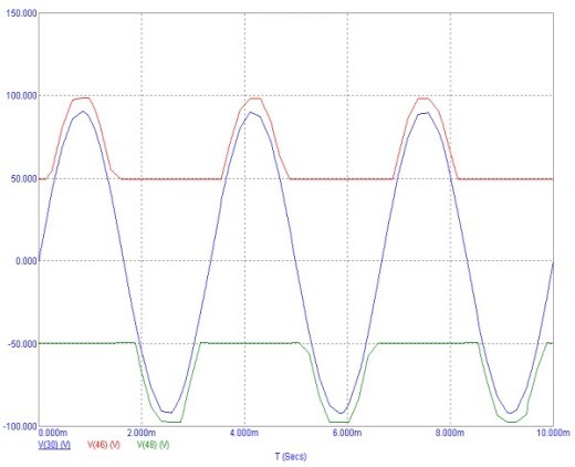
Figure 2. 
Figure 3
We sort of figured out how power should be supplied to the final stage, it remains to find out which set of elements to do this ...
To begin with, consider class H. Figure 5 shows a schematic diagram of a power amplifier operating in class H.

Figure 4 ENLARGE .
Blue indicates the voltage and power for a load of 4 ohms, red for a load of 8 ohms, the figure also shows the recommended power source. As can be seen from the diagram, its backbone consists of a typical class AB, however, the voltage is supplied to the amplifier from a higher-voltage "branch" of the supply, and the effect of the output signal on the supply voltage of the amplifier is reduced (the resistance R36, R37 is reduced, sometimes the value of these resistors has to be reduced up to 68 ohms, especially at powers above 1 kW), since when the "second floor" of the power supply is connected, a small surge is observed on the output signal, which not everyone can catch with the ear, but it affects the stability of the circuit quite seriously ...
The control of the power supplied to the final stages is carried out by comporators LM311, the threshold of which is regulated by trimming resistors R73 and R77. Correct tuning will require either VERY good hearing or, preferably, an oscilloscope.
After the comporators, there are transistor drivers that work directly on the gates of mosfites of different structures. Since the power control power mosfites operate in switch mode, the heat generated on them is quite low, for them the maximum current flowing through the open drain-source junction is much more important. For these purposes, we use transistors IRFP240-IRFP9240 for amplifiers up to 700 W, the same, but 2 in parallel for powers up to 1 kW and IRF3710-IRF5210 for powers over 1 kW.
Figure 5 shows a schematic diagram of a 1400 W class H power amplifier. The circuit differs from the previous version in that 6 pairs of transistors are already used in the final stage (4 pairs are needed for a 1000 W amplifier), and IRF3710-IRF5210 power control power switches.

Figure 5. ENLARGE
Figure 6 shows a schematic diagram of the Chameleon 600 G amplifier, operating in class G and with an output power of up to 600 W, both for a load of both 4 ohms and 8 ohms. In fact, the control of the "second floor" of the power supply is carried out by repeaters of the output signal voltage, only they are preliminarily supplied with an additional reference voltage of 18 volts, and as soon as the output voltage approaches the value of the "first floor" voltage by more than 18 volts, the repeaters begin to supply voltage from " second floor." The advantage of this circuitry is that there is no switching interference characteristic of class H, however, improving the sound quality requires quite serious sacrifices - the number of transistors in the control of the supply voltage of the final stage must be equal to the number of terminal transistors themselves and this will be practically at the OBR limit, i.e. e. Requires fairly good cooling.

Figure 6 ENLARGE
Figure 7 shows an amplifier circuit for power up to 1400 W box G, which uses 6 pairs of both terminal and control transistors (4 pairs are used for powers up to 1000 W)

Figure 7 ENLARGE
PCB drawings - full version - lie. Drawings in lay format, in jpg will be a little later...
The technical characteristics of the amplifiers are summarized in the table:
| Parameter name | Meaning |
| Supply voltage, V, two-level, no more | |
| Maximum output power into a load of 4 ohms: UM CHAMELEON 600 H UM CHAMELEON 1000 H UM CHAMELEON 1400 H UM CHAMELEON 600 G UM CHAMELEON 1000 G | |
| The input voltage is adjusted by selecting the resistor R22 and can be set to the standard 1 V. However, it should be noted that the higher the self-gain coff, the higher the THD level and the likelihood of excitation. | |
| THD for class H and output power 1400 W max THD for class G and output power 1400 W max At output power before turning on the "second floor" power THD level for both amplifiers does not exceed | 0,1 % |
| Recommended quiescent current of the penultimate stage a voltage of 0.2 V is set on resistor R32 or R35 by resistor R8 | |
| Recommended quiescent current of terminal transistors on any of the 0.33 Ohm resistors, the voltage is set to 0.25 V by resistor R29 | |
| It is recommended to adjust the protection on a real speaker by connecting the AC resistance of 6 ohms in parallel and achieving a steady glow of the VD7 LED at 75% of the maximum power |
Unfortunately, this amplifier has one drawback - at high supply voltages, the differential stage starts to heat up spontaneously due to too much current flowing through it. Reduce the current - increase the distortion, which is highly undesirable. Therefore, the use of heat sinks for transistors of the differential stage was applied:

READ FULLY ALL MATERIAL ABOUT SEMMETRIC AMPLIFIER
Course Curriculum
| newspaper number | Educational material |
| 17 | Lecture number 1. The main goals and objectives of the Olympiad movement in the context of modern education in Russia. The history of the chemical Olympiad movement in Russia. The system of chemical olympiads and creative competitions in Russia. The role of chemical Olympiads in education and science.(Tyulkov I.A., Arkhangelskaya O.V.) |
| 18 | Lecture number 2. Methods of preparation and holding of Olympiads of various levels. Organization of Chemistry Olympiads: from simple to complex. Preparatory, main and final stages of organizing Olympiads. The system of actors of the Olympiad, their role.(Tyulkov I.A., Arkhangelskaya O.V.) |
| 19 | Lecture number 3. Conceptual basis of the content of Olympiad problems. Approximate program of the content of various stages of Chemistry Olympiads: rigid boundaries or guidelines for preparation? Classification of Olympiad problems. Tasks of Chemistry Olympiads: from stage to stage, from round to round.(Tyulkov I.A., Arkhangelskaya O.V.) Test No. 1(Deadline - November 25, 2008) |
| 20 | Lecture number 4. A technique for solving problems involving a "chain" of transformations. Classification of problems with transformation schemes. Tactics and strategy for solving Olympiad problems with "chains". |
| 21 | Lecture number 5. Methods for solving problems in physical chemistry (1). Problems in thermochemistry. Problems using the concepts of "entropy" and "Gibbs energy".(Tyulkov I.A., Arkhangelskaya O.V., Pavlova M.V.) |
| 22 | Lecture number 6. Methods for solving problems in physical chemistry (2). Problems for chemical equilibrium. Problems in kinetics.(Tyulkov I.A., Arkhangelskaya O.V., Pavlova M.V.) Test No. 2(deadline - until December 30, 2008) |
| 23 | Lecture number 7. Methodical approaches to the implementation of experimental tasks. Classification of tasks of the experimental round. Practical skills necessary for the successful completion of experimental tasks.(Tyulkov I.A., Arkhangelskaya O.V., Pavlova M.V.) |
| 24 | Lecture number 8. Methodical principles of preparing schoolchildren for olympiads. The use of modern pedagogical technologies in preparation for olympiads of various levels. Tactics and strategy of preparation and participation in the Olympiads. Organizational and methodological work of the teacher-mentor. Methodical approaches to the preparation of Olympiad tasks. Olympiads as a means of improving the skills of teachers-mentors. The role of Internet communication and mass media in the exchange of pedagogical experience.(Tyulkov I.A., Arkhangelskaya O.V., Pavlova M.V.) |
| Final work. A brief report on the final work, accompanied by a certificate from the educational institution, must be sent to the Pedagogical University no later than February 28, 2009. (More details about the final work will be printed after lecture No. 8.) |
|
I.A. TYULKOV,
O.V. ARKHANGELSKAYA,
M.V. PAVLOVA
LECTURE #4
Methodology for solving problems,
including a "chain" of transformations
Classification of problems with transformation schemes
In the tasks of the All-Russian Chemistry Olympiad for schoolchildren at any stage and for any age parallel of the participants, there are always tasks with schemes of successive transformations of one substance into another, which characterize the relationship between the main classes of organic and inorganic substances. A multi-stage scheme for the transformation of one substance into another in a certain sequence is often called a "chain". In the "chain" part or all of the substances can be encrypted.
To perform these tasks, it is necessary to know the main classes of inorganic and organic compounds, the nomenclature, laboratory and industrial methods for their preparation, chemical properties, including products of thermal decomposition of substances, reaction mechanisms.
"Chains" is the best way to test a large amount of knowledge (in almost all sections of general, inorganic and organic chemistry) in one task.
Schemes of transformations of substances can be classified as follows.
1) By objects:
a) inorganic;
b) organic;
c) mixed.
2) By types or mechanisms of reactions (mainly in organic chemistry).
3)In the form of a "chain".
a) All substances are given without indicating the reaction conditions.
b) All or some substances are encrypted with letters. Different letters correspond to different substances, the reaction conditions are not indicated.
(In schemes, the arrows can point in any direction, sometimes even in both directions. And this is not a sign of reversibility! Such reactions, as a rule, contain different reagents.)
c) The substances in the scheme are fully or partially encrypted with letters and the reaction conditions or reagents are indicated.
d) In the diagrams, instead of substances, the elements that make up the substances are given in the corresponding oxidation states.
e) Schemes in which organic substances are encrypted in the form of gross formulas.
Schemes can be linear, branched, in the form of a square or other polygon (tetrahedron, cube, etc.).
Tactics and strategy for solving Olympiad problems with "chains"
In this lecture, we will stick to the classification of tasks in form presented in the "chain" of successive transformations of one substance into another.
In order to correctly solve any problem of compiling reaction equations according to the scheme, it is necessary:
1) put the numbers under or above the arrows - number the reaction equations, pay attention, which way arrows are directed in the chain of transformations;
2) decipher the substances represented by letters, properties or gross formulas (the answer should be motivated, i.e. it is necessary not only to write down the formulas of the deciphered compounds, but to give detailed explanations of the decryption);
3) write down (under the appropriate numbers) all the reaction equations;
4) carefully check whether the coefficients are set correctly;
5) write down the reaction conditions, if necessary.
There are many ways to transform one substance into another. For example, CuO can be obtained from Cu, Cu(OH) 2, CuSO 4, Cu(NO 3) 3, etc. Any correct solution. For some problems, alternative solutions are given.
Let's illustrate almost all types of "chains" that are given at the regional (III) stage. The level of these tasks is close to the program for applicants to chemical universities. Therefore, these will be examples not only from the sets of the regional stages of the All-Russian Olympiad, but also from the entrance exam tickets in chemistry at Moscow State University. M.V. Lomonosov. In addition, assignments from the Olympiads of recent years preceding these exams are used (for example, from the Conquer Sparrow Hills competition and the Lomonosov Olympiad). When solving tasks in which there are encrypted substances, detailed explanations of the decoding of a particular compound are given.
Let's start with the easiest tasks.
All substances are given without indication of reaction conditions
Task 1.
Fe 2 (SO 4) 3 -> FeI 2 -> Fe(OH) 2 -> Fe(OH) 3 -> Fe 2 O 3 -> Fe -> Fe 2 (SO 4) 3.
Solution
Let's number the chain:
To carry out the first reaction, both a reducing agent and a compound capable of removing the sulfate ion from the reaction sphere are needed at the same time. For example, barium iodide.
The third reaction requires an oxidizing agent. Most suitable is hydrogen peroxide, ie. only one reaction product is produced. Let's write the reaction equations.
1) Fe 2 (SO 4) 3 + 3BaI 2 = 2FeI 2 + I 2 + 3BaSO 4;
2) FeI 2 + 2NaOH = Fe(OH) 2 + 2NaI;
3) 2Fe(OH) 2 + H 2 O 2 = 2Fe(OH) 3;
4) 2Fe(OH) 3 = Fe 2 O 3 + 3H 2 O;
5) Fe 2 O 3 + 2Al \u003d 2Fe + Al 2 O 3;
6) 2Fe + 6H 2 SO 4 (50%) = Fe 2 (SO 4) 3 + 3SO 2 + 6H 2 O.
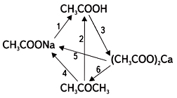
Task 2. Write the reaction equations corresponding to the following scheme:
Solution
1) CH 3 COONa + HCl = CH 3 COOH + NaCl;
2) 5CH 3 COCH 3 + 8KMnO 4 + 12H 2 SO 4 = 5CH 3 COOH + 5CO 2 + 8MnSO 4 + 4K 2 SO 4 + 17H 2 O;
3) 2CH 3 COOH + CaСO 3 \u003d (CH 3 COO) 2 Ca + H 2 O + CO 2;
4) CH 3 COCH 3 + 8NaMnO 4 + 11NaOH = CH 3 COONa + 8Na 2 MnO 4 + Na 2 CO 3 + 7H 2 O;
5) (CH 3 COO) 2 Ca + 2NaOH = 2CH 3 COONa + Ca(OH) 2
(CH 3 COO) 2 Ca + Na 2 CO 3 \u003d 2CH 3 COONa + CaCO 3;
6) (CH 3 COO) 2 Ca (tv.) \u003d CH 3 COCH 3 + CaCO 3.
Task 3.
Write the reaction equations corresponding to the following scheme:

Solution
1) 2СuCl + Cl 2 = 2CuCl 2;
2) CuCl (solid) + 3HNO 3 (conc.) = Cu (NO 3) 2 + HCl + NO 2 + H 2 O;
3) Cu + 4HNO 3 (conc.) = Cu(NO 3) 2 + 2NO 2 + 2H 2 O;
4) Cu + Cl 2 = CuCl 2;
5) 2Cl + 2NaOH + O 2 = 2CuO + H 2 O + 2NaCl + 4NH 3;
6) C 3 H 3 Cu (in reaction 6) can only be a salt of propyne (C 3 H 4), because alkynes with terminal
C =
The CH-group is CH-acids with which complexes of copper and silver react.
Cl+CH = C–CH 3 = CuC = C–CH 3 + NH 3 + NH 4 Cl;
7) 2C 3 H 3 Cu + 3H 2 SO 4 (conc.) = 2C 3 H 4 + 2CuSO 4 + SO 2 + 2H 2 O;
8) CuSO 4 CuO + SO 3
CuSO 4 CuO + SO 2 + 0.5O 2;
9) CuO + 2HCl = CuCl 2 + H 2 O;
10) CuCl + 2NH 3 (aqueous solution) = Cl;
11) C 3 H 3 Cu + 3HNO 3 (conc.) = Cu(NO 3) 2 + C 3 H 4 + NO 2 + H 2 O (in aqueous solution);
12) Cu + 2H 2 SO 4 (conc.) = CuSO 4 + SO 2 + 2H 2 O.
All or some substances are encrypted with letters.
The reaction conditions are not specified.
Task 4. The transformation scheme is given:

Write the equations for the reactions indicated by arrows. Name the unknown substances.
Solution
Determination of unknown substances. CuSO 4 can be obtained by dissolving Cu, CuO or Cu 2 O in sulfuric acid. Cu 2 O is not suitable, because this substance is already in the chain. Thus, the first two reactions can be the following:
1) 2Cu 2 O + O 2 = 4CuO (X 1 = CuO);
2) СuO + H 2 SO 4 = CuSO 4 + H 2 O.
1) Cu 2 O \u003d Cu + CuO
or Cu 2 O + H 2 \u003d Cu + H 2 O (X 1 \u003d Cu);
2) Cu + 2H 2 SO 4 (conc.) = СuSO 4 + SO 2 + 2H 2 O.
It is known that freshly prepared copper(II) hydroxide oxidizes aldehydes. As a result of the reaction, an orange precipitate of Cu 2 O is obtained. Therefore, X 2 - Сu (OH) 2.
3) CuSO 4 + 2NaOH \u003d Na 2 SO 4 + Cu (OH) 2;
4) 2Cu(OH) 2 + R–CHO = R–COOH + Cu 2 O + 2H 2 O
RCHO + NaOH + 2Cu(OH) 2 = RCOONa + 3H 2 O + Cu 2 O.
Answer. X 1 is either copper or copper (II) oxide; X 2 is freshly prepared copper (II) hydroxide.
Task 5(Department of Chemistry, Moscow State University, 1998). Write the equations of chemical reactions corresponding to the following sequence of transformations:

Solution
The starting (key) link in this scheme is the substance E - aldehyde. Consider reactions 4, 5, and 1. It is known that a qualitative reaction for aldehyde is its interaction with freshly prepared Cu(OH) 2 . The result is a carboxylic acid corresponding to the aldehyde and Cu 2 O. It is likely that the substance F is Cu 2 O, since substance B should be obtained from substance F. Since substance B is also obtained during the thermal decomposition of Cu (OH) 2, it is clear that B is CuO. It follows that the substance C is H 2 O. D is an alcohol, which is reduced with the help of CuO to an aldehyde. And finally, reaction 2: alcohol (D) is obtained by hydration of an alkene (in the scheme, alcohol is obtained from water!), Which means that it must contain at least two carbon atoms in the chain.
A - Cu(OH) 2 ; B—CuO;
C - H 2 O; D - RCH 2 CH 2 OH;
E, RCH 2 CHO; F - Cu 2 O.
Reaction equations:
1) Cu(OH) 2 CuO + H 2 O;
2) H 2 O + R–CH=CH 2 = R–CH 2 –CH 2 OH;
3) R–CH 2 –CH 2 OH + CuO = R–CH 2 –CH = O + Cu + H 2 O;
4) R-CH 2 -CH \u003d O + 2Cu (OH) 2 \u003d R-CH 2 -COOH + Cu 2 O + 2H 2 O
RCHO + NaOH + 2Cu(OH) 2 = RCOONa + 3H 2 O + Cu 2 O;
5) 2Cu 2 O + O 2 4CuO
Cu 2 O \u003d Cu + CuO.
Task 6 (for independent solution).
Write the reaction equations corresponding to the following scheme of successive transformations:

Name the substances X 1 and X 2 .
Substances in the scheme are fully or partially encrypted with letters
and specified flow conditions or reagents
Task 7. Write the equations of chemical reactions corresponding to the sequence of transformations:
Identify unknown substances.
Solution
When iron reacts with hydrochloric acid, iron(II) chloride is obtained. (This is due to the fact that hydrogen at the time of release does not allow iron to oxidize to an oxidation state of +3.) In the 2nd reaction, it is oxidized to, and sulfuric acid can be reduced to sulfur or SO 2. The resulting solution of iron(III) salts has an acidic environment, because These are salts formed by a weak base and a strong acid. When soda is added - a salt of a strong base and a weak acid - a joint hydrolysis occurs, which proceeds to the end, i.e. a precipitate (Fe(OH) 3) and gas (CO 2) is formed. The hydrolysis of each salt enhances the hydrolysis of the other.
X 1 - FeCl 2; X 2 - Fe 2 (SO 4) 3 and FeCl 3 (mixture);
X 3 - Fe (OH) 3 (or CO 2, or NaCl and Na 2 SO 4).
Reaction equations:
1) Fe + 2HCl = FeCl 2 + H 2;
2) 6FeCl 2 + 4H 2 SO 4 = Fe 2 (SO 4) 3 + 4FeCl 3 + S + 4H 2 O
6FeCl 2 + 6H 2 SO 4 = Fe 2 (SO 4) 3 + 4FeCl 3 + 3SO 2 + 6H 2 O;
3) 4FeCl 3 + Fe 2 (SO 4) 3 + 9Na 2 CO 3 + 9H 2 O \u003d 6Fe (OH) 3 + 9CO 2 + 12NaCl + 3Na 2 SO 4.
Task 8. Write the equations of chemical reactions corresponding to the following chain of transformations:
Solution
We number the reaction equations in the "chain":
Reaction 1 is the trimerization of acetylene (a typical method for producing benzene). Next (reaction 2) is the Friedel-Crafts alkylation of benzene in the presence of the Lewis acid AlBr 3 . Bromination in the light (reaction 3) proceeds in the side chain. An alcoholic solution of alkali in reaction 4 is a reagent for obtaining alkyne from a dihalogenated alkane. Next comes the exchange reaction (reaction 5): hydrogen at a triple bond in alkyne and a silver ion in an ammonia solution of silver oxide. And, finally (reaction 6), the resulting silver phenylacetylenide enters into an exchange reaction with methyl iodide, as a result of which the carbon chain is lengthened.
Reaction equations:
1) 3C 2 H 2 \u003d C 6 H 6;
2) C 6 H 6 + C 2 H 5 Br \u003d C 6 H 5 -C 2 H 5 + HBr;
3) C 6 H 5 -C 2 H 5 + 2Br 2 \u003d C 6 H 5 -CBr 2 -CH 3 + 2HBr;
4) C 6 H 5 -CBr 2 -CH 3 + 2KOH \u003d C 6 H 5 -C = CH + 2KBr + H 2 O;
5) C 6 H 5 -CCH + OH \u003d AgC = C–C 6 H 5 + 2NH 3 + H 2 O;
6) AgC = C–C 6 H 5 + CH 3 I = AgI + CH 3 –C = C–C 6 H 5 .
So, encrypted substances:

In the diagrams, instead of substances, elements are given,
constituent substances in the corresponding oxidation states
Task 9. Write the reaction equations illustrating the transformation scheme:
Solution
We number the reaction equations in the chain:
In reaction 1, the Fe(II) compound is oxidized to the Fe(III) compound (these can be salts, hydroxides, oxides, etc.). Dichromates or chromates, permanganates, halogens, etc. can be taken as an oxidizing agent.
In reaction 4, iron is reduced from the +3 oxidation state to a simple substance. Usually, metallic iron is obtained by reducing its oxides (for example, chromium or aluminum at high temperatures - metallothermy).
Iron(III) oxide can be obtained by thermal decomposition of its salts or hydroxide (reaction 3). Reaction 2 is most likely exchange. Reaction 5 - the interaction of metallic iron with a non-oxidizing acid (HCl, HBr, CH 3 COOH, etc.).
Consider three of all possible solutions to this problem.
First option:
1) 2Fe 2+ + Cl 2 = 2Fe 3+ + 2Cl -;
2) Fe 3+ + 3OH - = Fe (OH) 3;
3) 2Fe(OH) 3 = Fe 2 O 3 + 3H 2 O (calcination);
5) Fe + 2H + = Fe 2+ + H 2.
Second option:
1) 2Fe(OH) 2 + H 2 O 2 = 2Fe(OH) 3;
2) Fe(OH) 3 + 3HNO 3 = Fe(NO 3) 3 + 3H 2 O;
3) 4Fe(NO 3) 3 = 2Fe 2 O 3 + 12NO 2 + 3O 2 (calcination);
4) Fe 2 O 3 + 2Al = Al 2 O 3 + 2Fe;
5) Fe + 2HCl \u003d FeCl 2 + H 2.
Third option:
1) 4FeO + O 2 = 2Fe 2 O 3;
2) Fe 2 O 3 + 3H 2 SO 4 = Fe 2 (SO 4) 3 + 3H 2 O;
3) 2Fe 2 (SO 4) 3 \u003d 2Fe 2 O 3 + 6SO 2 + 3O 2 (calcination);
4) Fe 2 O 3 + 2Al = Al 2 O 3 + 2Fe;
5) Fe + 2HCl \u003d FeCl 2 + H 2.
Schemes in which organic substances
encrypted as gross formulas
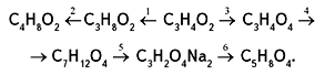
Task 10. Write the reaction equations corresponding to the following transformation scheme:
In the equations, indicate the structural formulas of the substances and the reaction conditions.
Solution
The key link in the chain is a substance with the formula C 3 H 4 O 2. According to reaction 1, the substance is reduced (an additional four hydrogen atoms appear in the gross formula), and according to reaction 3, it is oxidized (an additional two oxygen atoms appear in the formula). It is most likely that C 3 H 4 O 2 is propandial (CHO–CH 2 –CHO), then C 3 H 4 O 4 is propanediolic acid (COOH–CH 2 –COOH), and C 3 H 8 O 2 is propanediol- 1.3 (CH 2 OH–CH 2 –CH 2 OH). Arguing similarly (calculating changes in the number of atoms in a molecule), we conclude that reaction 4 produces propanediolic acid double ethyl ester (C 2 H 5 OOC–CH 2 –COOC 2 H 5). Reaction 5 - alkaline hydrolysis of the ester, which results in C 3 H 2 O 4 Na 2 - salt (NaOOC - CH 2 -COONa), and reaction 6 with the help of halomethane produces propanediolic acid double methyl ester (CH 3 OOC - CH 2 –COOCH 3).
Reaction 2 - interaction of propanediol-1,3 with methanal to form dioxane-1,3 
Reaction equations:


Task 11.
Write the reaction equations corresponding to the following transformation scheme:

In the equations, indicate the structural formulas of substances and the conditions for the reactions to occur.
(Sign S N indicates that the reaction proceeds by the mechanism of nucleophilic substitution.)
Solution
We number the reaction equations in the chain:

The molecule of the substance C 8 H 9 Cl, obtained through one stage from benzene, apparently contains a phenyl radical - this follows from the ratio of carbon and hydrogen in the compound (C 6 H 5 C 2 H 4 Cl). Then X can be a substance C 6 H 5 -CH 2 -CH 3, which turns into C 6 H 5 -C 2 H 4 Cl when exposed to chlorine in the light; or X may be a substance C 6 H 5 -CH=CH 2 that gives C 6 H 5 C 2 H 4 Cl when exposed to HCl. In both cases, chlorine goes to the secondary carbon atom C 6 H 5 CHCl–CH 3.
Substance Y is obtained by the reaction of nucleophilic substitution of chlorine, most likely by an OH group (reaction 3). Then reaction 4 will be a dehydration reaction. C 8 H 8 in the context of this task, probably C 6 H 5 –CH=CH 2 . In this case, reaction 5—oxidation at the double bond with permanganate in a neutral medium—results in the formation of a diol with the empirical formula C 8 H 10 O 2 . And, finally, the appearance in the final "chain" formula (compared to substance Z) of four more carbon atoms, four hydrogen atoms and two oxygen atoms means the esterification reaction of diol and acetic acid.
Reaction equations:
1) C 6 H 6 + CH 2 \u003d CH 2 C 6 H 5 -C 2 H 5;
2) C 6 H 5 –C 2 H 5 + Cl 2 C 6 H 5 –CHCl–CH 3 + HCl;
3) C 6 H 5 –CHCl–CH 3 + NaOH + H 2 O = C 6 H 5 CH(OH)–CH 3 + NaCl;
4) C 6 H 5 –CH(OH)–CH 3 C 6 H 5 CH=CH 2 + H 2 O;
5) 3C 6 H 5 CH=CH 2 + 2KMnO 4 + 4H 2 O = 3C 6 H 5 CH(OH)–CH 2 (OH) + 2MnO 2 + 2KOH;
6) C 6 H 5 CH(OH)–CH 2 (OH) + 2CH 3 COOH = ![]()
In conclusion, we give examples of tasks that were presented at the federal district* And final stages of the All-Russian Olympiad for schoolchildren in chemistry. At these stages, the transformation chains become more complex. In addition to the chain itself, additional information about the properties of encrypted substances is given. To decipher substances, it is often necessary to carry out calculations. At the end of the text of the task, it is usually proposed to answer several questions related to the properties of substances from the "chain".
Task 1 (federal district stage 2008, 9th grade).
« A, B And IN are simple substances. A reacts quickly with B when heated to 250 °C, forming dark red crystals of the compound G. Reaction B With IN after preliminary initiation proceeds very violently, leading to the formation of a colorless substance D, gaseous under normal conditions. G, in turn, can react with IN at a temperature of 300-350 ° C, while the red crystals turn into a white powder E and a connection is formed D. Substance A reacts with D only at a temperature of about 800 ° C, while forming E And IN. Substance G can easily be sublimated at reduced pressure and temperatures below 300 ° C, but when heated above 500 ° C, its vapors decompose to form a substance B and again connections E.

1. Identify Substances A–E.
2. Write the equations for all the mentioned reactions in accordance with the diagram.
3. How will the substances interact? G And E with aqueous solutions of sodium sulfide and iodide, with an excess of concentrated potassium cyanide solution? Write reaction equations.
4. Write the equations of reactions occurring during the interaction of substances G, D And E with concentrated nitric acid.
Solution
1. Let's pay attention to percentages: connection D, consisting of two elements B And IN, gaseous and contains only 2.74% IN. Such a small percentage indicates that either the atomic mass of the element IN very small, or in the formula D high index on element B. Given that D at n.o. is a gas, it is most likely that IN is hydrogen. Let's test our hypothesis. If the composition D express the formula H X E at, That
2,74: (97,26/M E) = X : at.
Note that the connections where at is not equal to 1, cannot be obtained by direct interaction of the element with hydrogen during the "violent reaction after preliminary initiation". Rearranging the equation, we get M E = 35.5 X, which has a unique reasonable solution for X= 1. Thus, IN- hydrogen, B- chlorine.
Let's define the substance E, which includes 55.94% chlorine. It is formed during the reaction of a simple substance A with hydrogen chloride, and hydrogen is released, which suggests: E- chloride of the element that forms a simple substance A. For connection ECl x :
(55,94/35,45) : (44,06/M E) = X.
From here M E = 27.92 X. At X= 1 and 3, respectively, silicon (28) and krypton (84) are obtained, but this contradicts their valence capabilities and the condition of the problem, but at X= 2, iron (56) is obtained, which, in reaction with hydrogen chloride, actually forms FeCl 2 . During the direct reaction of iron with chlorine, another chloride is formed - FeCl 3.
So, encrypted substances:
A– Fe; B– Cl2; IN– H2;
G– FeCl 3 ; D– HCl; E- FeCl 2 .
2. Reaction equations in the chain:

3. 2FeCl 3 + 3Na 2 S = 2FeS + S + 6NaCl;
FeCl 2 + Na 2 S \u003d FeS + 2NaCl;
2FeCl 3 + 2NaI \u003d 2FeCl 2 + I 2 + 2NaCl
(reactions are possible:
2FeCl 3 + 6NaI \u003d 2FeI 2 + I 2 + 6NaCl
6FeCl 3 + 18NaI = 2Fe 3 I 8 + I 2 + 18NaCl);
FeCl 3 + 6KCN = K 3 + 3KCl;
FeCl 2 + 6KCN = K 4 + 2KCl.
4. FeCl 3 + 4HNO 3 \u003d Fe (NO 3) 3 + NOCl + Cl 2 + 2H 2 O;
3HCl + HNO 3 \u003d NOCl + Cl 2 + 2H 2 O;
2FeCl 2 + 8HNO 3 \u003d 2Fe (NO 3) 3 + 2NOCl + Cl 2 + 4H 2 O.
Task 2 (federal district stage 2007, 10th grade).
"Under A–E(except IN) substances containing transition metals are encrypted.
Quantitative composition of substances A And WITH:
A:(Cu)=49.3%, (O)=33.1%, (S)=16.6%.
C:(Co)=50.9%, (O)=34.5%, (S)=13.8%.
1. Identify Substances A–E and write the reaction equations.
2. In which case in the above scheme the substance IN it turns out amorphous and in what crystalline? Propose one alternative method for the synthesis of crystalline and amorphous substances IN.
3. What is the trivial name of the substance D?»
Solution
1. Adding up all the given mass fractions (as for a substance A, and for the substance WITH), we will not get 100%. This means that these substances contain at least one more element!
Substance A:
Given the small mass fraction of the unknown element, we can assume that it is hydrogen. Then the gross formula of the compound A: Cu 3 S 2 O 8 H 4, or Cu 2 SO 3 CuSO 3 2H 2 O.
Substance WITH:
Similarly to the previous case, we can assume that here the unknown element is hydrogen. Then the formula of the substance WITH will be Co 2 (OH) 2 SO 3 .
Substance IN is Al(OH) 3 . When aluminum sulfate reacts with sodium sulfite, amorphous aluminum hydroxide is formed. In the second case, when triethylammonium chloride reacts with Na, crystalline aluminum hydroxide is formed.
When interacting IN And WITH when heated, cobalt aluminate is formed - Co (AlO 2) 2.
In an alkaline environment, the reduction of the permanganate ion goes either to the oxidation state of +6 or to +5, respectively E- K 2 MnO 4 or K 3 MnO 4.
A– Cu 2 SO 3 CuSO 3 2H 2 O; B– Al(OH) 3 ; C– Co 2 (OH) 2 SO 3; D– CoAl 2 O 4 ; E- K 2 MnO 4 or K 3 MnO 4.
Reaction equations in the "chain":
1) 3CuSO 4 + 3Na 2 SO 3 \u003d Cu 2 SO 3 CuSO 3 2H 2 O + 3Na 2 SO 4 + SO 2;
2) 3Na 2 SO 3 + Al 2 (SO 4) 3 + 3H 2 O \u003d 2Al (OH) 3 + 3Na 2 SO 4 + 3SO 2
(along with aluminum hydroxide, basic sulfates of various compositions will be present in this phase, but it is traditionally believed that amorphous aluminum hydroxide is formed);
3) Na + Cl \u003d Al (OH) 3 + NaCl + NEt 3 + H 2 O;
4) 2CoSO 4 + 2Na 2 SO 3 + H 2 O \u003d Co 2 (OH) 2 SO 3 + SO 2 + 2Na 2 SO 4;
5) Co 2 (OH) 2 SO 3 + 4Al (OH) 3 2CoAl 2 O 4 + SO 2 + 7H 2 O;
6) 2KMnO 4 + Na 2 SO 3 + 2KOH = 2K 2 MnO 4 + Na 2 SO 4 + H 2 O
KMnO 4 + Na 2 SO 3 + 2KOH = K 3 MnO 4 + Na 2 SO 4 + H 2 O.
2. Solutions of aluminum salts have an acidic environment:
3+ H + + 2+ 2H + + + .
When an alkali (or an aqueous solution of ammonia), carbonates, or hydrocarbonates is added, an increase in the pH of the solution leads to a shift in the equilibrium to the right and the polymerization of aquahydroxo complexes through bridging hydroxo and oxo groups into polynuclear complexes. As a result, a product of composition Al 2 O 3 x H 2 O ( X > 3) (amorphous precipitate with no constant composition).
Amorphous aluminum hydroxide production method:
Al 2 (SO 4) 3 + 6KOH \u003d 2Al (OH) 3 + 3K 2 SO 4
Al 2 (SO 4) 3 + 6KHCO 3 \u003d 2Al (OH) 3 + 3K 2 SO 4 + 6CO 2.
The method for obtaining crystalline aluminum hydroxide is to slowly pass CO 2 through a solution of sodium tetrahydroxoaluminate:
Na + CO 2 \u003d NaHCO 3 + Al (OH) 3.
In the second case, a product of a certain composition is obtained - Al (OH) 3.
3. Cobalt aluminate has the trivial name "thenar blue".
Task 3 (final stage 2008, 10th grade).
"The scheme below shows the transformations of compounds A–TO containing the same element X.
Additionally known:
Element X occurs naturally as a mineral A(content by mass: Na - 12.06%,
X - 11.34%, H - 5.29%, the rest is oxygen);
B- a binary compound containing 15.94% (by mass) X;
IN is a colorless gas with an air density of about 1;
Compound D used in medicine in the form of an alcohol solution;
d-modification Z similar to graphite in physical properties;
Substance AND is widely used in organic synthesis as a reducing agent;
Molecule TO(almost flat) has an axis of symmetry of the third order (with a complete rotation around this axis of symmetry, the molecule TO reproduces its position in space three times); in the 1H NMR spectrum of the compound TO two signals are observed.
1. Define an element X. Support your answer with a calculation.
2. Give formulas of compounds A–AND. Name the mineral A.
3. Draw Structural Formula TO and name this connection.
4. Write the equations for all the reactions shown in the diagram.
5. Write the reaction equation X(amorphous) with a mixture of concentrated nitric and hydrofluoric acids.
6. What explains the similarity of physical properties -modifications Z with graphite?
Solution
1. binary substance B formed by the interaction of a mineral A with calcium fluoride in the presence of concentrated sulfuric acid. It can be assumed, that B in addition to element X contains fluorine. Given that the valence of fluorine in compounds is 1, B can be written as XF n. Let's define element X:
![]()
Where M r(X) is the relative atomic mass of the element X, n- valence X in the compound B. From this equation we find
M r(X) = 3.603 n.
Looping through the values n from 1 to 8. The only reasonable option is obtained when n = 3: M r(X) = 10.81, i.e. element X is boron, (and the substance B– boron trifluoride BF 3).
2. Find the composition of the substance A.
those. Na 2 B 4 H 20 O 17, or Na 2 B 4 O 7 10H 2 O, - mineral "borax" (substance A).
When boron trifluoride is reduced with sodium hydride, a colorless gas is formed IN, most likely representing the hydrogen compound of boron. Since the density IN by air about 1, molecular weight IN is close to 29, therefore, substance B is diborane B 2 H 6 ( M r = 28).
Further interaction of diborane with an excess of NaH in ether leads to the formation of a complex hydride widely used in organic synthesis as a reducing agent, sodium tetrahydroborate Na (substance AND).
Burning diborane produces boron oxide, G– B 2 O 3 , the reduction of which with metallic aluminum leads to the formation of amorphous boron. Boron oxide reacts with water, resulting in the formation of orthoboric acid H 3 BO 3 (substance D, in the form of an alcohol solution is used in medicine under the name "boric alcohol"). Boric acid reacts with concentrated hydrofluoric acid to give a complex acid, which, after treatment with sodium hydroxide solution, is converted to sodium tetrafluoroborate Na (compound E).
Consider the interaction of boron trifluoride with gaseous ammonia. BF 3 is a typical Lewis acid (electron pair acceptor); the ammonia molecule has an unshared pair of electrons, i.e. NH 3 can act as a Lewis base. When boron trifluoride reacts with ammonia, an adduct of the composition BF 3 NH 3 is formed (compound AND) (the covalent bond between boron and nitrogen atoms is formed by the donor-acceptor mechanism). Heating this adduct above 125°C leads to the formation of boron nitride BN (compound Z).
3. When diborane reacts with gaseous ammonia when heated, the product is formed TO containing hydrogen, boron, and probably nitrogen. Molecule TO has a flat structure, its high symmetry indicates a possible carbon analogue of this compound - benzene. However, in order for the molecule TO Since there were two types of hydrogen atoms and there was a third-order symmetry axis, it is necessary to alternately place nitrogen and boron atoms in the "benzene" ring instead of carbon atoms (Fig.). Compound TO called "inorganic benzene" (borazol).

4. The equations for the reactions described in the problem are:
1) Na 2 B 4 O 7 10Н 2 О + 6CaF 2 + 8H 2 SO 4 (conc.) = 4BF 3 + 2NaHSO 4 + 6CaSO 4 + 17H 2 O;
2) 2BF 3 + 6NaH = B 2 H 6 + 6NaF;
3) B 2 H 6 + 3O 2 = B 2 O 3 + 3H 2 O;
4) B 2 O 3 + 2Al = Al 2 O 3 + 2B;
5) B 2 H 6 + 2NaH 2Na;
6) B 2 O 3 + 3H 2 O \u003d 2H 3 BO 3;
7) H 3 BO 3 + 4HF (conc.) \u003d H + 3H 2 O,
H + NaOH \u003d Na + H 2 O;
8) BF 3 + NH 3 = BF 3 NH 3;
9) 4BF 3 NH 3 BN + 3NH 4 BF 4 ;
10) 3B 2 H 6 + 6NH 3 2B 3 N 3 H 6 + 12H 2 .
5. B (amorphous) + 3HNO 3 (conc.) + 4HF (conc.) = H + 3NO 2 + 3H 2 O.
6. Note that the BN particle is isoelectronic to the C 2 particle, the sum of the covalent radii of the boron and nitrogen atoms is approximately equal to the sum of two covalent radii of the carbon atom. In addition, boron and nitrogen have the ability to form four covalent bonds (three by the exchange mechanism and one by the donor-acceptor mechanism). Accordingly, BN also forms two structural modifications - graphite-like (-modification) and diamond-like (-modification). That is why -BN is very similar in physical properties to graphite (refractory, lubricating properties).
Literature
Tasks of the All-Russian Olympiads in Chemistry. Ed. acad. RAS, prof. V.V. Lunina. M.: Exam, 2004, 480 p.; Chemistry: formulas for success in entrance exams. Tutorial. Ed. N.E. Kuzmenko, V.I. Terenina. M.: Publishing House of Moscow State University, Nauka, 2006, 377 p.; Chemistry-2006: Entrance examinations at Moscow State University. Ed. prof. N.E. Kuzmenko and prof. V.I.Terenina. M.: Publishing House of Moscow State University, 2006, 84 p.; Entrance examinations and Olympiads in Chemistry at Moscow University: 2007. Ed. prof. N.E. Kuzmenko and prof. V.I.Terenina. M.: Publishing House of Moscow State University, 2008, 106 p.; Tasks of the All-Russian Olympiad in Chemistry of the federal district and final stages 2003–2008. Internet. http://chem.rusolymp.ru ; www.chem.msu.ru
* Until 2008, inclusive, VOSh(x) was held in five stages: school, municipal, regional, federal district and final. - Note. authors.